
Shielding Fundamentals
Magnetic shielding materials re-direct a magnetic field so it lessens the field’s influence on the item being shielded. Shielding does not eliminate or destroy magnetic fields, nothing does. It does, however, provide an easy path for the magnetic field to complete its path. You may think of it as a magnetic field conductor.
This leads to what type of material can provide a path for magnetic fields and thus provide shielding. Since the field is attracted to the shielding material it stands to reason that if a magnet is attracted to the material (ferromagnetic material) it can provide some amount of magnetic shielding. That’s right, your refrigerator door can provide some magnetic shielding. Don’t waste your time with lead or wood.
With the above said, let’s discuss the design of a magnetic shield. We know that our shield will be dependent on the strength of the magnetic field it is in and how much of that field it occupies (the shield’s physical size). We also know that the shield conducts or re-directs the magnetic field through the material from which the shield is made. Hence, the more material in the shield the more magnetic field it can re-direct. Putting all of this together we get a starting point for designing a shield.
B = (1.25 x D x Ho) ÷ (t)
Where: D = a physical dimension depicting the shield’s size in inches. For a cylinder it would be the diameter and for a rectangular
shield use the diagonal.
Ho = the strength of the field to be shielded (Gauss)
t = the thickness of the shielding material (inches)
B (flux density in the shielding material in Gauss) is the strength of the magnetic field that needs to be re-directed within the shield itself. It is important because once we estimate it we are able to see whether the shield can handle that much field. We do this by referring to the B-H (Flux Density – Magnetizing Force) curve for the shielding material (below).
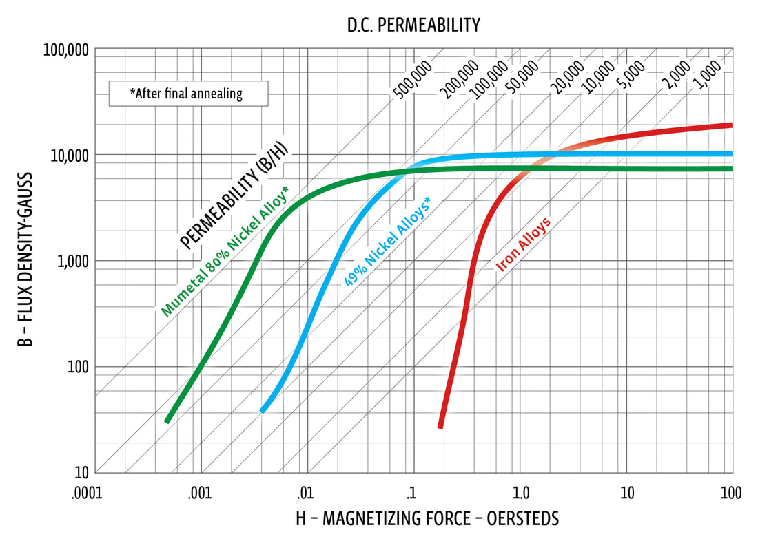
Entering the curve read across the B (flux density) to where it intersects the Mumetal (we’ll limit discussion to MuMetal) material line. At this intersection estimate the permeability from the permeability curves running at an angle. Notice from the B-H curve that as the flux density increases the permeability also increases up to a point where there is a slight hump (often referred to as the “knee”) after which the curve levels out and the permeability decreases. Once you enter the “knee” you are approaching the region where the material is becoming “saturated” (region of decreasing permeability). You don’t want to design very far into the “knee”. If this happens start over and calculate a new B by increasing the thickness of the material. Permeability can be thought of, unscientifically, as an indication how well a material can conduct a magnetic field. Once the permeability has been determined use it to estimate how much the magnetic field has been reduced on the other side of the shield (attenuated) using the formula below.
A = (µ x t) ÷ (D)
Where: A = the attenuation ratio (original field strength / shielded field strength)
µ = permeability (from the B-H curve)
t = shield wall thickness (inches)
D = shield’s physical diameter or diagonal (inches)
Keep in mind that the calculations can provide a first step in designing a shield but they are not exact and should not be construed as a Law of Nature. Neither are the properties of the shielding materials going to be exact from one batch to the next. Nothing will take the place of using these formulas to make a prototype and testing the prototype under real world conditions.
Now that we’ve had a brief discussion of magnetic fields and shielding let’s put the above information to work to design a prototype shield. Rather than going through all of the steps above, although you are welcome to, we’ll use Magnetic Shield’s Calculator to simplify the process. All you need to do is input D, the diameter or diagonal in inches that describes the size of the shield and HO, the strength of the field in Gauss where the shield will be located. Magnetic Shield’s Calculator will do the rest and give you an estimate of the strength of the shielded field for each standard thickness of our annealed foil and sheet. There are some restrictions. We have limited “D” to a range of ¼” to 12”. If you go outside of this range you will notified that “D” is either too large or too small. If you get the message that the field is too high it means you have entered into the “knee” of the B-H curve and will need a thicker material. Don’t hesitate to contact us if you have a shield that doesn’t fit the above criteria. Larger shields and higher magnetic fields are common. We’d just like to be a little more involved with them.
Let’s Get Practical
Many scientific calculations (solutions to problems) assume that something goes to infinity. Our Calculator is based on this assumption. Now it’s very difficult to work with a magnetic shield that is infinitely long so use these guidelines: If your shield must be open ended (a can with the ends cut off) extend the shield one “D” dimension on each open end. So if you have a part that is 3” long going into a 1” diameter open ended shield try to make the shield 5” long (1”+3”+1”). If you’re able to cap one end then shorten the shield by one “D” or you don’t need to lengthen it at all if both ends are closed. It won’t be as efficient as an infinitely long shield but it is a viable compromise.
Magnetic fields are vector quantities, which means they have both magnitude and direction. Optimal shielding takes place when the magnetic field is perpendicular to the axis of the shield. Magnetic Shield Corporation’s Calculator assumes this is the case. If not, you won’t get the amount of shielding calculated.
Often times it is necessary to put openings into a shield to feed in wiring or for some other reason. Keep in mind that any openings or leak points reduce the effectiveness of the shield. This is another good reason to build a prototype.
Magnetic Shield’s Calculator provides a theoretical selection for the thickness of the shield based on the shield being infinitely long, without openings and in a magnetic field acting perpendicular to its axis. Of course none of this is likely to be true in the real world so consider selecting a thicker material if your application warrants it. From a manufacturing point of view there other considerations which may also make it necessary to go thicker.
Although Mu-Metal comes in various thicknesses it is a rather soft material and may prove to be difficult to work with if it is too thin. You should keep that in mind making your selection. Anything below 0.020” thick is difficult to weld other than with spot welding. If you are going to weld the material use the Stress annealed rather than the Perfection and furnace anneal the finished part. We can provide annealing services for your shield.
Even if you start with a perfect part the annealing process can distort it. This is especially true as the parts get larger. Make the shield as simple and "dimensionally forgiving" as possible. For parts that don’t require a lot of shearing and bending use the Perfection annealed material as long as you aren’t going to do any welding or drawing. Our Perfection material will come to you already annealed and its magnetic properties won’t be significantly reduced with normal sheet metal processes as long as it isn’t drawn or welded.
If the shield is going to be used to support a part, either inside or out, take the following into consideration. MuMetal is soft and not extremely strong after annealing. Magnetic Shield does not recommend tapping it in order to attach brackets or other parts. Welding the bracket to the shield would be preferred and it should be made from a non-ferromagnetic material (300 Series stainless steel would be an example). Keep the part to be shielded from touching the shield. It doesn’t need to be far from the shield but we prefer they don’t touch. Be careful not to build a precision watch. Annealing will unpredictably and uncontrollably make dimensional changes to the fabricated part. Depending on the load to be supported by the shield consider using a thicker wall for additional strength.
Over several decades, Magnetic Shield Corporation has performed hundreds of laboratory tests and calculated thousands of shielding equations – all in an effort to continually validate the theoretical application of magnetic interference control in both AC and DC applications and aid engineers in shield design. Theory behind the B-H curve is well documented, and it remains an effective reference tool. By use of the B-H curve, our MuMETAL shielding has been developed and refined to offer the most effective shielding characteristics for a variety of applications and markets. The B-H curve depicts our material capabilities to attenuate and shield a wide range of magnetic fields.
In reality, the source field (Ho) may not be readily recognized and its ultimate effect unknown. However, with proper measurement equipment and study, the source field intensity and direction can be measured. One of the most important design questions is whether the source field is internal or external, and which field is most economical and practical to shield. Internal interference is created by designed-in components located within a circuit, system, enclosure, piece of equipment or room. External interference is created by unwanted nearby fields radiating from items such as power lines, circuits, electrical enclosures, transformers, electro-magnetic machinery and the earth’s magnetism.
Both internal and external interference can usually be nullified by shielding with the proper alloy. Once the source field and affected area(s) are determined, shielding calculation and alloy selection begins. Material selection is a function of field intensity, type of field and required attenuation. There is no known material that blocks magnetic fields without itself being attracted to the magnetic force. Magnetic fields can only be redirected, not created or removed. To do this, high-permeability shielding alloys are used. The magnetic field lines are strongly attracted into the shielding material. Mu-Metal is used primarily in fields of low intensity because of their high attenuation characteristics. Soft iron finds application in fields of high intensity because of its high magnetic saturation characteristics. If used in combination, the iron layer is placed closest to the source of interference, with the Mu Metal closest to the component being shielded.
There are many factors to consider before shield design: appropriate shielding alloy and thickness, most effective shape, size and configuration, penetrations for inputs and outputs to a shielded device, and location of the shield relative to the source. In all cases, theory helps determine the best material, yet hands-on evaluation becomes the most important determining factor; providing critical information for final design and fabrication of an effective shield.